Navigating the Electrical Landscape: A Comprehensive Guide to Electrical System Diagrams
Related Articles: Navigating the Electrical Landscape: A Comprehensive Guide to Electrical System Diagrams
Introduction
In this auspicious occasion, we are delighted to delve into the intriguing topic related to Navigating the Electrical Landscape: A Comprehensive Guide to Electrical System Diagrams. Let’s weave interesting information and offer fresh perspectives to the readers.
Table of Content
Navigating the Electrical Landscape: A Comprehensive Guide to Electrical System Diagrams

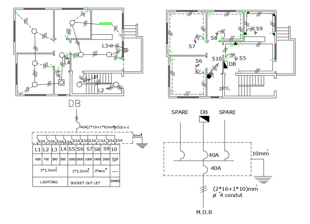
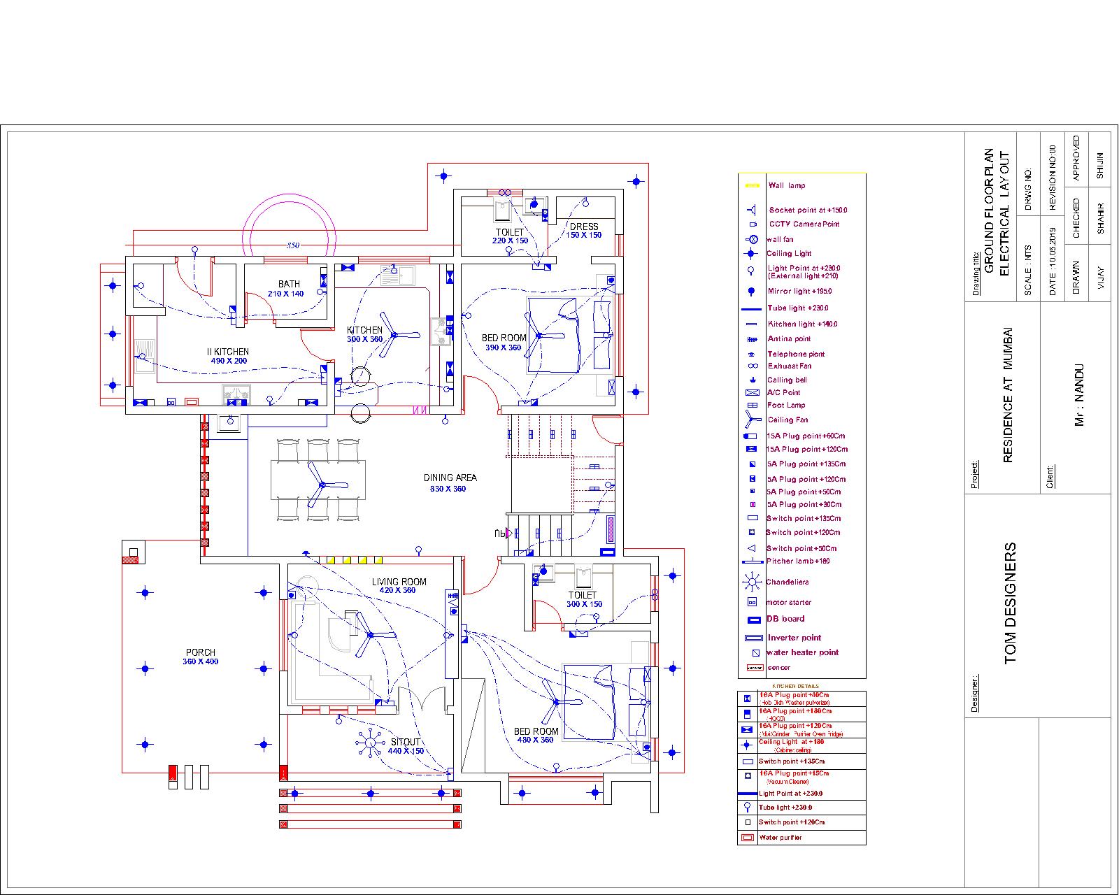
Electrical systems, whether in a small appliance or a sprawling industrial complex, possess inherent complexity. Understanding their intricate workings requires a visual representation: an electrical diagram. These diagrams, also known as electrical schematics, wiring diagrams, or single-line diagrams, depending on the level of detail, serve as crucial tools for design, installation, troubleshooting, and maintenance. They provide a standardized method for documenting the interconnected components and pathways of electrical energy flow within a system.
Different types of diagrams cater to various needs. Schematic diagrams prioritize the logical relationships between components, showing the flow of electricity and control signals without necessarily reflecting the physical layout. Wiring diagrams, on the other hand, emphasize the physical arrangement of wires and components, providing a more accurate representation of the system’s physical construction. Single-line diagrams, often used for larger systems like power grids, simplify complex networks by representing each component with a single line, focusing on the main power flow paths.
The core components depicted in these diagrams include power sources (generators, batteries), loads (motors, lights, appliances), protective devices (circuit breakers, fuses), control devices (switches, relays), and interconnecting wiring. Each component is represented by a standardized symbol, ensuring consistency and ease of interpretation across different diagrams. These symbols are defined by industry standards, such as those published by the Institute of Electrical and Electronics Engineers (IEEE) and other relevant organizations. Adherence to these standards is crucial for clarity and unambiguous communication.
The Importance of Accurate Documentation
Accurate and well-maintained diagrams are paramount for several reasons. During the design phase, they enable engineers to plan and optimize the system, ensuring efficient power distribution and minimizing potential hazards. Detailed documentation helps anticipate potential problems and implement preventative measures. Furthermore, it aids in selecting appropriate components and sizing wires for safe and reliable operation.
During installation, diagrams serve as a roadmap for electricians, guiding them through the process of connecting components and ensuring correct wiring. This minimizes errors and reduces the risk of electrical faults or safety hazards. Proper installation, guided by accurate diagrams, contributes to the longevity and reliability of the electrical system.
Troubleshooting and maintenance become significantly easier with access to comprehensive diagrams. When a fault occurs, technicians can quickly identify the affected section of the system by tracing the path of electricity on the diagram. This reduces downtime and minimizes repair costs. Regular maintenance, guided by the diagram, helps prevent potential failures and extends the lifespan of the system.
Beyond Simple Representations: Advanced Applications
The application of these visual aids extends beyond basic systems. In sophisticated industrial settings, diagrams play a vital role in process control and automation. They are integral to programming programmable logic controllers (PLCs) and designing supervisory control and data acquisition (SCADA) systems, which manage and monitor complex industrial processes. These diagrams facilitate the integration of various sensors, actuators, and control systems, ensuring efficient and safe operation.
Furthermore, advancements in software have led to the development of interactive and dynamic diagrams. These digital representations can simulate the behavior of the electrical system under various conditions, enabling engineers to test different scenarios and optimize performance before physical implementation. This capability allows for more efficient design iterations and minimizes the risk of costly errors.
Frequently Asked Questions
-
Q: What software is typically used to create electrical diagrams?
- A: A variety of software packages are available, ranging from simple drawing programs to specialized electrical CAD software. Popular choices include AutoCAD Electrical, EPLAN Electric P8, and SEE Electrical. The choice depends on the complexity of the system and the specific needs of the user.
-
Q: How frequently should electrical diagrams be updated?
- A: Diagrams should be updated whenever changes are made to the electrical system, such as adding new components, modifying wiring, or replacing equipment. Regular audits of the diagrams against the physical system are recommended to ensure accuracy.
-
Q: What are the consequences of using inaccurate or outdated diagrams?
- A: Using outdated or inaccurate diagrams can lead to incorrect installations, hazardous situations, inefficient operation, and increased maintenance costs. In extreme cases, it can even result in equipment damage or personal injury.
-
Q: Are there industry standards for creating electrical diagrams?
- A: Yes, several industry standards exist to ensure consistency and clarity in the representation of electrical systems. Adherence to these standards is essential for effective communication and collaboration among engineers, technicians, and other stakeholders.
Tips for Effective Use and Maintenance of Electrical Diagrams
- Clearly label all components and wiring: Use consistent and unambiguous labeling to avoid confusion.
- Maintain a revision history: Track changes made to the diagram over time to maintain accuracy.
- Use standardized symbols: Adhere to industry standards for symbols to ensure consistency and clarity.
- Regularly review and update: Compare the diagram to the physical system to ensure accuracy.
- Store diagrams securely and accessibly: Maintain a central repository for all diagrams related to a system.
- Use version control: Track changes and allow for easy rollback to previous versions.
Conclusion
Electrical diagrams are indispensable tools for understanding, designing, installing, troubleshooting, and maintaining electrical systems. Their importance spans a wide range of applications, from simple household circuits to complex industrial processes. Accurate, well-maintained diagrams are essential for ensuring safety, efficiency, and reliability. By adhering to industry standards and best practices, organizations can leverage the full potential of these visual aids, promoting effective communication and minimizing the risk of errors. The ongoing evolution of software and digital tools further enhances the capabilities of these diagrams, making them even more valuable in the design and management of modern electrical systems.


Closure
Thus, we hope this article has provided valuable insights into Navigating the Electrical Landscape: A Comprehensive Guide to Electrical System Diagrams. We thank you for taking the time to read this article. See you in our next article!